Fuel Injector Drivers
Created Feb 2017 Updated May 2024
Fuel Injector Drivers: Peak and Hold and Saturated
The Problem:
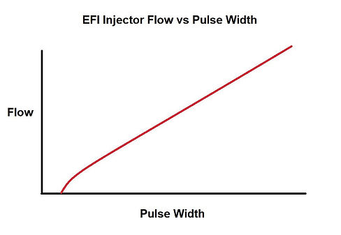
Back in the 1970s, while doing EFI research at Mellon Institute, one of my engineering projects was to find out why fuel injector flow was inconsistent at low pulse widths. Flow when the injector was held steady open was very consistent and easy to measure, but it was not as predictable when the injector was pulsed, and the shorter the pulse width, the less consistent the flow. Here’s a simple plot of fuel flow vs. pulse widths.
The Basics:
One side of the injector is connected to + battery power. This is usually via a relay that only provides power if the ECU is ready to start the engine. The injector turns on or opens when the ECU provides a ground signal to the other injector terminal. Predicted fuel flow is a function of the pulse width that the ECU provides. Current flow through the injector is a function of its coil impedance. Low impedance is usually less than 2 ohms and high impedance is usually above 10 ohms.

Note that the injector just sat there with no flow at short pulse widths. This is called injector opening dead time. It was caused by the inertia of the pintle valve itself trying to offset the fuel pressure and is dramatically affected by the operating voltage. Injector dead-time tables only handle this opening phase. If the injector can flow more fuel than the engine requires, the ECU might need to operate the injector at short pulse widths at idle when fuel demand is low. This can cause erratic idle characteristics merely because too large an injector was selected.
So What To Do:
This would seem that you already know all you need to know, but that is not the case. A fuel injector is just an electric solenoid that opens a pintle valve. It's a magnetic coil that creates a lot of inductive "flux" when the current is on, and the injector is flowing fuel, but when power is removed to shut off the injector, the collapsing magnetic flux field creates a reverse polarity current that slows down the process. The more power that was present when the injector was held on, the more flux was created, and the slower the injector turns off. It's physics! This reverse inductive voltage spike could be a relatively high voltage that can also induce electrical noise into wires of close proximity. “No biggie,” I said. “I’ll just clamp that reverse voltage with a diode.”
That was a disaster! The reason is basic electronic fundamentals. When the magnetic flux field around a coil collapses, the reverse polarity spike happens, but if you slow down the release of that stored energy, everything slows down until that energy has been dissipated. A diode clamped the voltage but it also slowed down the injector closing time. We thought all we had to handle was the opening time, but now also had to handle the closing time too.

Everyone thought all we would need was a simple ON/OFF transistor to switch the current on and off. This simple type of injector driver is called a saturated driver because the transistor is either totally on or saturated when the injector is activated. If the injector’s impedance is high (DC ohms > 8 ohms), its coil inductance is low, and the current and flux energy levels are also low. The lower the flux level, the faster and more predictable the injector turns off. So, a high-impedance injector is good? Maybe.
But more horsepower means more fuel flow. This requires a larger solenoid and more current, resulting in more flux, and everything worsens. This type of injector is called a Low-Impedance injector. Low impedance injectors (DC ohms < 2 ohms) were a real problem because they required much higher currents; therefore, the stored flux energy was high, the reverse inductive spike was higher, and the injector closing time was longer and inconsistent. But you needed a low-impedance injector for higher fuel flows and typically higher fuel pressures to overcome. An often overlooked secondary problem was the voltage drop in the wiring simply because of Ohm's law. A single 2-ohm low-impedance injector will draw 7 amps (I=E/R 14 volts/2 ohms = 7 amps). In a V8 engine, if the injectors are at 75% duty cycle, the total current that the wiring must support will exceed 40 amps! Wow. Better install that bigger alternator.
If we had to use a low-impedance injector, the “Eureka moment” was when we realized that although a full high current peak pulse was required to minimize the opening dead time, we could back way off on the current once the injector was open. Since this “hold current” is much lower than the opening current, the stored flux energy is also much lower, so the injector closes at a fast, consistent rate, which also causes minimal noise spikes. This type of injector driver is called a Peak and Hold driver. But you still need bigger wires to minimize voltage drops.

Summary:
Since high-impedance injectors minimize electrical requirements, there has been a trend to design high-Z injectors that can support higher fuel flows. Some companies, such as FIC (Fuel Injector Clinic), only build high-Z injectors and can still support flows approaching 300 lbs/hr.
Injector driver technology has improved to provide Peak and Hold driver technology if required. A shortcoming can be if you don't know what the hold level should be for your particular injector. Holley provides a separate Injector Driver module that I always recommend to my low-impedance injector clients. It's flexible enough to handle almost all Low-Z injectors, and it also offloads the main ECU from having to provide that massive current that has to make it back through the ground somehow. A separate driver provides a separate path for that ground current.
